Len’s approach to building a scale RC helicopter was to do it all himself, with the exception of power unit, radio and electronics. He would typically build a mould to construct the fuselage, and make his own mechanics, frame and rotor blades.
Here, are his words, in describing the build process of a scale fuselage.
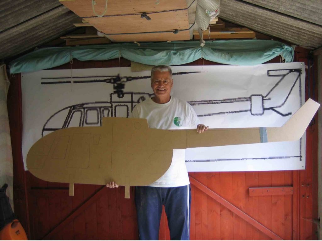
Step 1: Initial outline
“I start out by taking a scale 3 view diagram and enlarging it to suit both the mechanics we would like to use and the overall size of the model we want to create. From this enlarged diagram we then cut out a profile from MDF board.
Step 2: Creating a solid 3D model
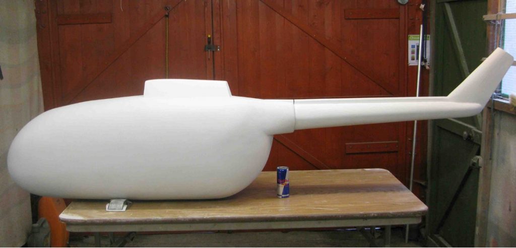
The next step is to create a solid model. I do this by cutting out formers of the side profile of the model and gluing into place. Having a plastic kit of the model being built helps in making the side profile accurate. The space between the formers is now filled in with foam to give a rough shape of the body
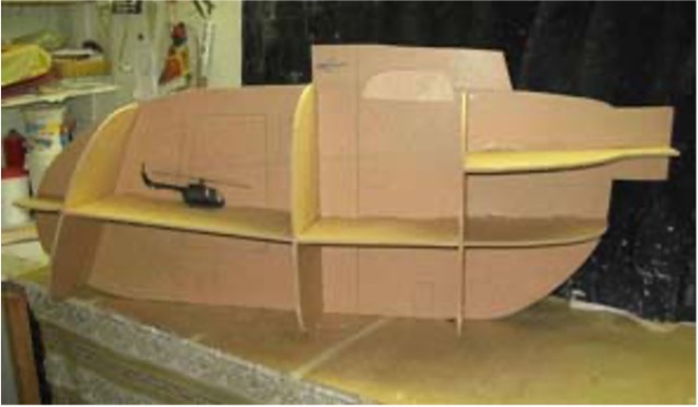
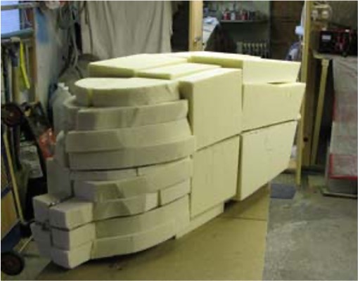
This is carved to shape and the result covered in car body filler which is then sanded to shape. I make constant reference to the 3 view diagram and the formers to get the profile in all 3 views right.
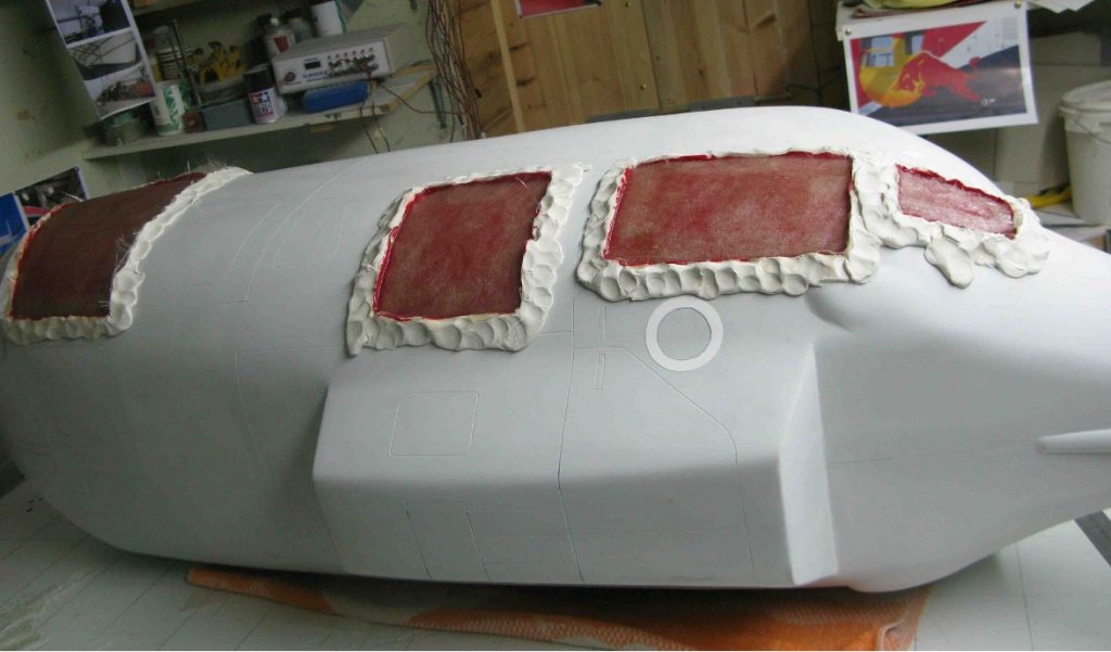
Onto this smoothed body I put in much of the scale detail such as panel lines as I can.
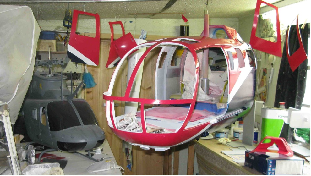
Step 3: Create the Moulds
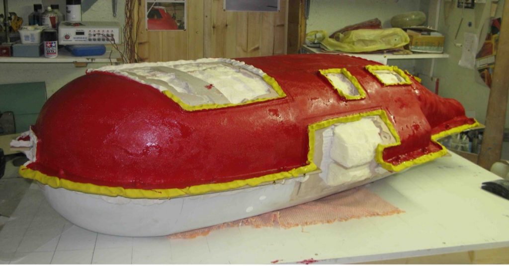
I now decide on where the mould is to be split for easy release e.g. tail removal, door openings etc. and the subsequent insertion of mechanics. I build these areas up with a layer of plasticine and put on a layer of gel coat and fibreglass matting to produce the moulds. These are then used to create the actual part which is then fitted back onto the plug after cutting out the area where it fits.
This continues until all the plug has been turned into moulds. (The red panels are the moulds in production)
Step 4: Create Body Kit
From the moulds I can now create a complete body shell using clear gel coat and epoxy resin with cloth. This creates a 'kit' of parts that is both light and strong. I reinforce any areas that are either weak or where stresses build up with Kevlar cloth and resin.
The following photo shows the completed tail and tail mould - notice pegs on either side of the mould for aligning sides.
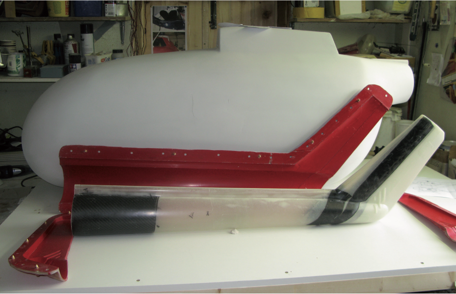
The different moulded parts can now be assembled.
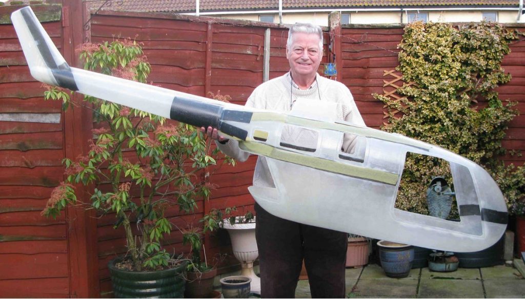
The result is not only accurate, but also very light. In the above photo, the total weight of the basic BO-105 fuselage is around 2 kilos.
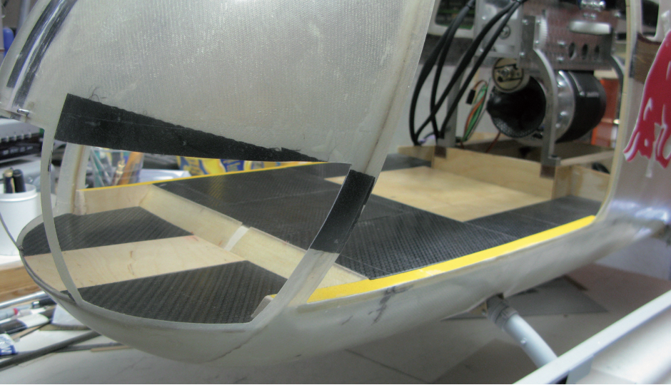
Step 5: Fit Mechanics and Engine
I now start putting the model together taking care to ensure engine and mechanics are well supported and easy to access for maintenance. Here I have installed the floor and temporarily fitted the mechanics and turbine to ensure everything fits.
My next job is to tackle the doors. I make mine so that the handles actually work and operate a rod mechanism that locks into both the top and bottom of fuselage. I use thin brass sheet silver soldered to a small brass tube for the handle. This tube then passes through the door to which another small plate is silver soldered, which will be attached to a rod. It’s a bit fiddly but well worth it when you see the result. I’ve also been known to add a small, powerful magnet to make sure they stay closed in flight.
I also make my own door hinges and louvres from brass sheet as I find most commercial hinges far too big to give a true scale appearance. As well as having two ‘normal’ doors, the BO105 has two large rear sliding doors that give access to the cabin and one huge cargo door at the rear. I spent many hours working out how to achieve this but was very pleased with the result.
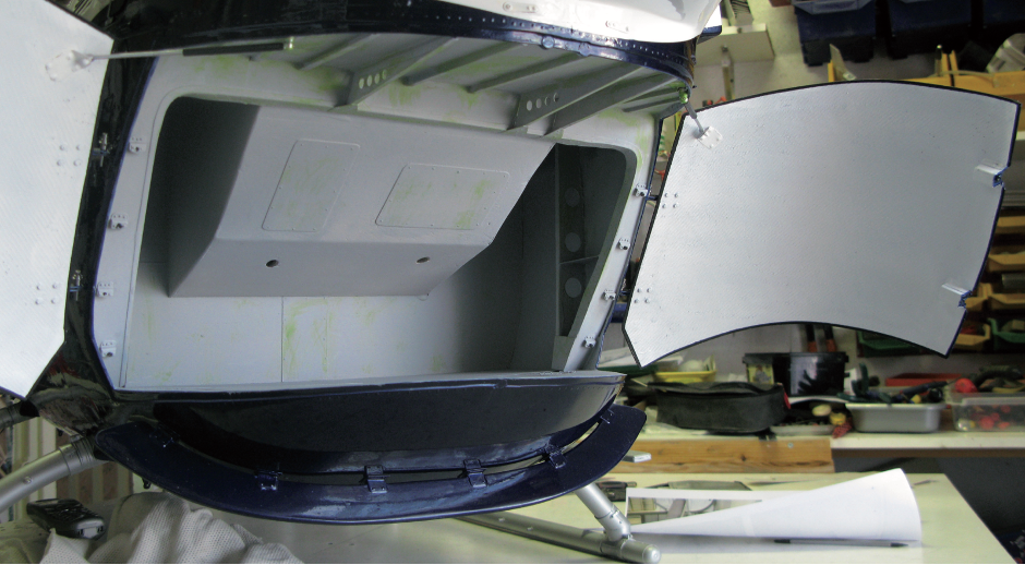
The above photo was taken after the model had been completed and painted.
The next task for me is to fit the tail boom to the main body. If this is to be removable then it means installing a coupling that enables the tail drive to easily connect simply by pushing the two sides together. It also means installing internal flanges so that the tail can be bolted together inside of the main body. This will require internal access to the bolts but arranged in a way that they cannot be seen from the outside. I do this by making a panel on the body near the coupling to be removable so that I can get access to the bolts with a suitable driver.
Step 6: Electrical
On my model I wanted to have the lighting replicate the exact sequence of lights of the full size Red Bull machine. When I saw the full size version I made a note of what lights flashed and when. Back at home I sourced the right colour lights and an electronic circuit that gives the exact sequence I required.
I fit in the wiring by using adhesive cable ties to keep the wires in place and where they cannot be accidentally cut. I put plugs on those lights going to the tail fins so that the fins can be easily removed. I also make up wiring looms for any remote servos and again make sure that the wiring is clearly labelled and neatly installed. Where I have working features such as moving joysticks, flashing lights, etc. I install a separate battery and in some models these are operated by a second receiver so I can keep my main receiver and batteries dedicated to flying the model.
I arrange for all switches and charging plugs to be mounted on a strong panel that is usually hidden behind a removable grill. By doing this there are no loose leads to get in the way, and starting the model is a simple, straight-forward affair.
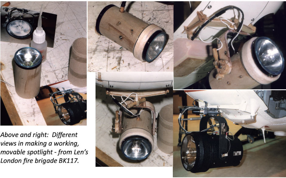
I love to build spotlights that are held within the body of the fuselage, but on command will swivel down and come on. These add a certain ‘wow’ factor and are surprisingly easy to do.
In making these I first find a cardboard roll that is the right diameter for the body. For a large search-light this may be a toilet-paper roll, while for a small light this may be the tube from a baking foil roll. The cardboard roll is then stiffened by soaking it in cyno. Mirrorlight ply is then wrapped around the outside to form the tube which can then be cut to the right length..
I use balsa wood to make the front surround and back of the tube, and the reflector and bulb from a torch to make the light. For a really bright light I use 6-volt halogen lamps made for flush- mounted ceiling lights. These come with an integral reflector so I only have to make up a cable to attach to the bulb.
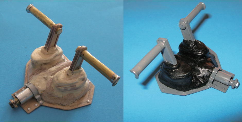
For the bracket holding the lamp, I make a solid former and then laminate layers of mirrorlight ply in a U-shape until the thickness I want is built up. This produces a very strong, yet light bracket. I also do the same with the mounting bracket that is fitted to the fuselage floor. I then add rivets, tiny nuts and bolts, and copper wires to mimic the detail of the full size unit. This is then mounted into the fuselage where servos can move the light left, right, up down, as well as turning the light on and off.
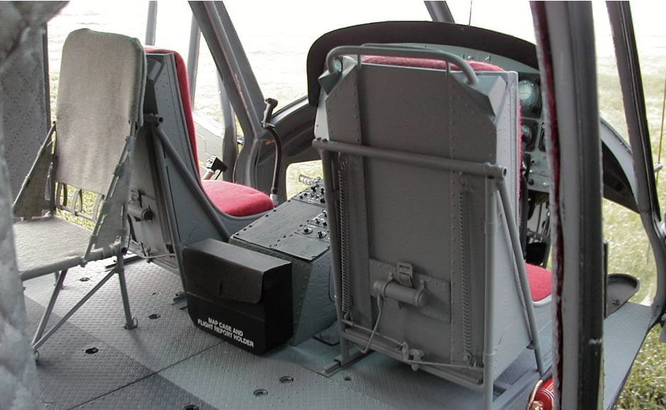
Step 7: Detail Interior/exterior
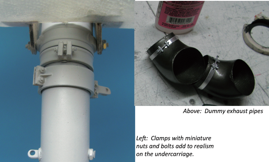
Scale detail is copied as accurately as possible from detailed photos made of the full size. I like to use tiny nuts and bolts to help with realism. It’s very fiddly, but worth the effort.
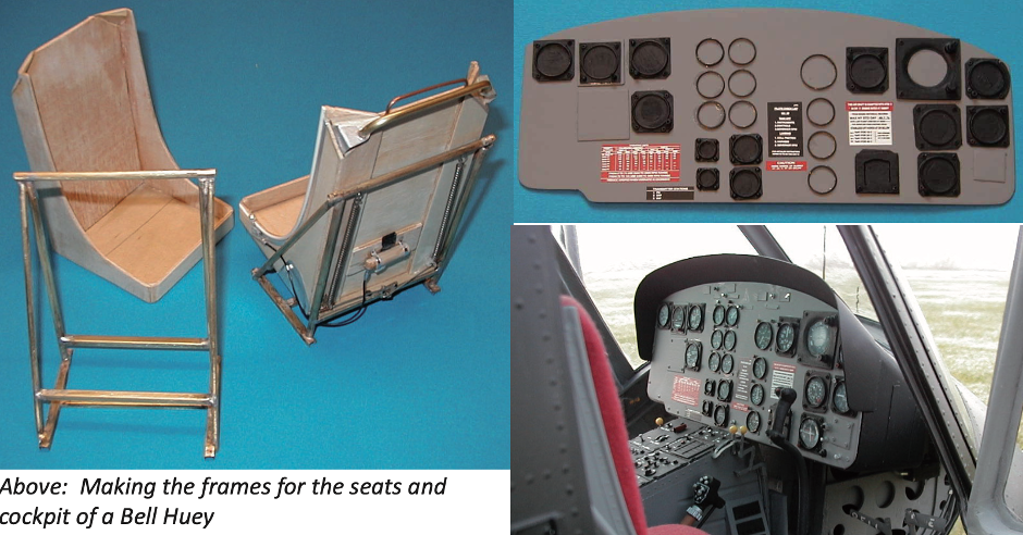
The difference between a good model and a scale model in my mind is all down to the interior. It’s fairy easy to make a model that replicates the external appearance of a full size machine but the builders expertise is only shown when the inside is as good as the real thing. Two things conspire against the builder - the lack of space due to the necessary placement of mechanics, engine and radio systems, and the cramped nature of that space which makes it very difficult to work on.
Many commercial fuselages only allow for the very front of the cabin to have any scale detail and quite often the scale interiors they provide are not very good. For this reason I build my own fuselages, which tend to be on the large size. However, if you do have a commercial fuselage you can still make a great job of the interior – but it will usually mean throwing away what was provided and starting afresh.
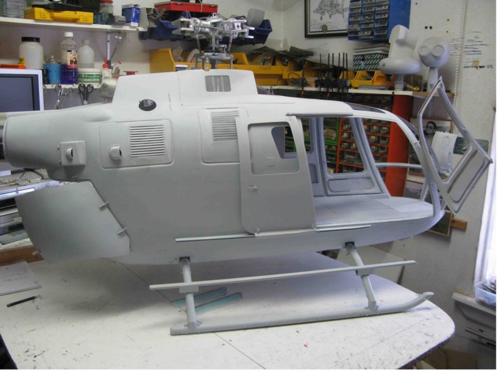
Step 8: Painting
The model is rubbed down, degreased and has a good undercoat applied. If the model is to have multiple colours such as the case with the Red Bull machine, I always put on the lightest colour first. In my case this was white and so I sprayed the whole machine white. I do this by first applying a light or dust coat, wait 10-15 minutes until tacky and then put on a wet coat. This is left to dry overnight.
When it is dry I mask up where the next lighter colour is to go – for the Red Bull this was red. I make sure that all the areas I want to stay white are completely covered. The next colour is then sprayed on. I repeat the masking and spraying process for the next lightest colour and so on until all the colours have been applied.
When all the paint has dried I then spray on a clear laquer coat. If you are like me and don’t want to feel the edges between the different colours then you should put on the clear laquer coat on top of each colour as you do them. Then the edges should be treated to a 1200 grit wet-and-dry rub making sure that you don’t break through the laquer coat.
On the Red Bull BO105, there are a number of graphics including lettering and a small cartoon character. The cartoon was far to small to mask up and spray so what I did was to enlarge the photo I had taken of it to the actual size I wanted for the model. It was then printed out onto the best quality photo paper and cut out by hand. I then carefully scrape the back of the photo to remove as much of the paper as I dare. Damping down the back of the photo can help with the paper removal. When I first used this technique I would often ruin two or three photos before I had one that was OK. I must admit I tend to get it right first time these days.
The resulting image is then attached to the fuselage by applying a solid adhesive such as Prit- Stick to the back of the photo. This is then laquered to protect it. On some intricate large designs you can also create a photoshop image and have this sent away to a company who can then make a mask from it, which makes the masking up a lot easier.
With miniature writing I enlarge a photo of the area six or seven times larger than I want. I have a friend who then turns this into a Letraset image at the right size, which can then be rubbed onto the finished model and laquer applied.
Once all the graphics and paintwork has been completed, I put on one or two final clear coats of laquer.
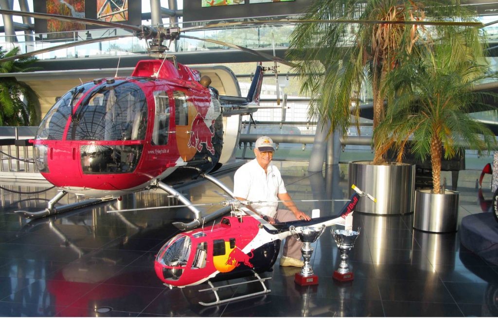
Step 8: Test Fly
The model is now finished and ready for it’s maiden flight that will expose different issues to be fixed before entering a competition. Here is a photo of the completed BO105 next to the original full size helicopter kept in Austria.